DHT22 Temperature and Humidity Sensor
Introduction

A DHT22 sensor (Temp and Humidity) |
So looking for a temperature sensor, i came accross with this wonderfull sensor which measures not only the temperarure
of the air, but also it's humidity with very accurate approach to it's measurements.
As a matter of fact this sensor can measure temperatures from -40 to +125oC with an accuracy of ±0.2oC
and relative humidity from 0-100%RH with an accuracy of ±5%(Max) !!!
This sensor uses a single pin for it's communication, which makes it versatille for a variety of microcontrollers with few pins.
Another neat feaure is that the sensor has an operating voltage between 3.3-6V which is perfect solution for many microcontrollers
even from them that operate on low voltage levels.
According datasheet it has a long range transmittion 20m, (at 5V, without defining cable diameter) and an extremely low power
consumption of 1mA (when meausing and sending data), and 20-50μA (when it is in stand-by mode).
Closing i would also like to say that there is another sensor named DHT11 which is the same as the DHT22, with minor differences
that i will mention below. Have in mind that the sensor named as AM2302 is the same as DHT22 , but still i haven't understood
if there is any difference between them.
Also the company that manufacturing these sensors is ASAIR. Have a look at their webpage to discover another intersting sensors.
Video
Follow me on tweeter and stay tuned with Electronicsgate.com
Pinout Description
There is no much to say about the pinout. It has been kept same pinout pattern to all of these sensors which is awesome !!!.
Later on we will see that besides the same pinout they also use the same communication technique, which is amazing, especially when you want to do
an upgrade to your project without changing anything to your pcb.
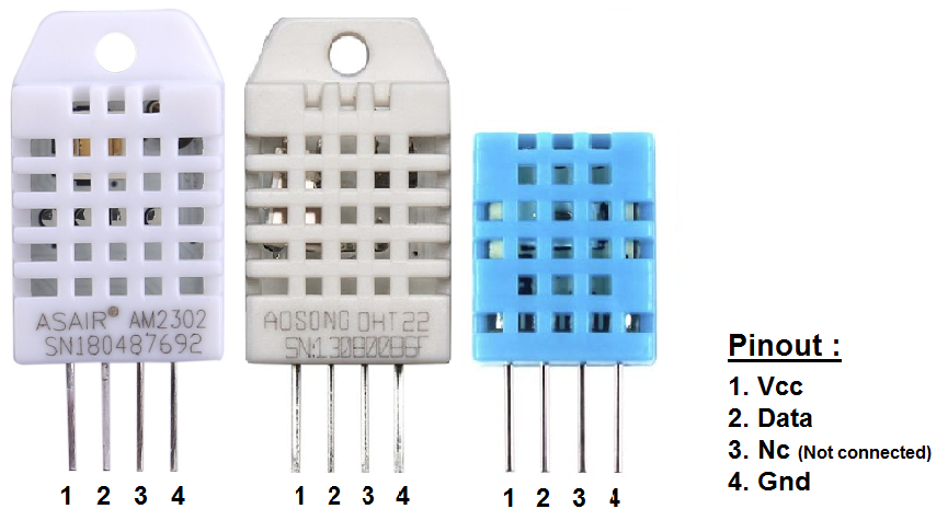
It has 4 pins as it is shown below (fig2) , where 2 of them are used for power supply , 1 of it for the communication, and the remaining is left open.
As you can see from below, DHT11 is slightly smaller in compasison the other two, but the pins have exactly the same spacing and functionallity.

|
| Power supply pin. It can handle voltages from 3.3 to 6VDC |
||
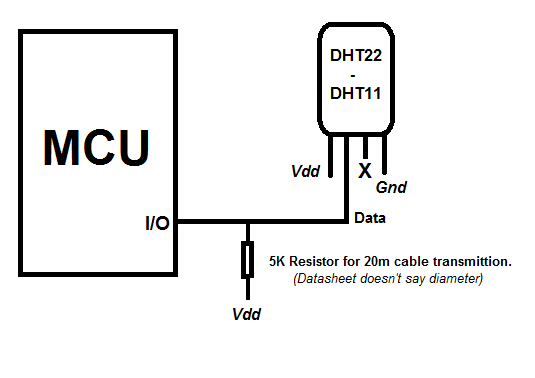
| Data communication pin. (Input/Output) Requires a pull up resistor of 4.7K | ||
| Not connected.(Float) | ||
| Ground pin. | ||
Theory Of Operation
These sensors are constisted of two different sub-sensors, one for meausing temperature and one for measuring humidity.
The temperature measument is made by a high-precision NTC thermistor, which changes it's resistance according temperature.
There are two types of thermistors NTC and PTC.
NTC stands for “Negative Temperature Coefficient”,
which means that it's resistance decreases with an increase of the temperature.
PTC does the opposite, it increases it's resistance, with an increase of the temperature. “Positive Temperature Coefficient”.
As for the humidity it uses a capacitive wet sensor, usually it consists of two electrodes and between them a
conductive plastic polymer, whereas it increases it's resistance propotional to the relative humidity.
Higher relative humidity decreases the resistance, and lower relative humidity increases the resistance.
At this point we should mention that each sensor is calibrated in a very accurate humidity and temperature calibration room,
and the calibration coefficients are stored in the form of a program in the microcontroller.
So during a read, these calibration coefficients are called within the sensor, the internal microcontroller process the data
and sends you the final accurate measurement at data pin. (Awesome because in some other sensors i do it manually)
Below are both sensors disassembled...

|
Technical Characteristics
By first sight, you can notice a pretty obvious difference which is the size. But is this the only difference that these modules have?

|

|
On the left side there are the characteristics of each module taken by their datasheet.
It is pretty obvious that DHT22 has more accurate measuments at temperature and humidity than DHT11, and a
wider temperature operating range.
As for the drawbacks, DHT22 is a little bit bigger than DHT11, and it has slower sample rate in comparison DHT11, which is 0.5Hz (every two seconds) for DHT22 and 1Hz (every second) for DHT11.
Also one big advantage for buying a DHT11 sensor is it's cost, which is 1/3 of DHT22.
But honestly i would prefer DHT22 just because it's accuracy.
DHT22 Communication
(Timing)
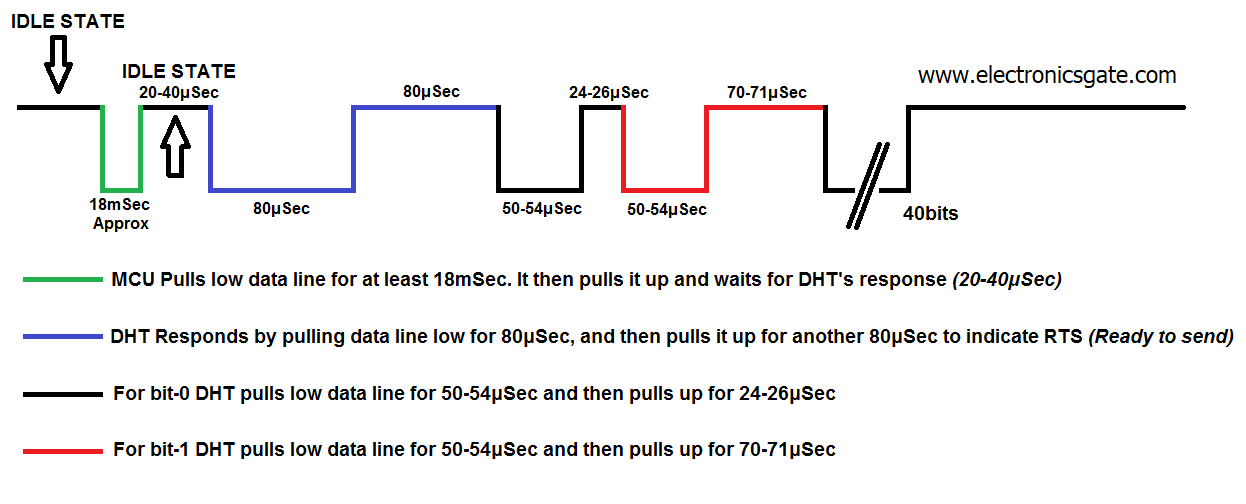
Below i have re-created the communication data timing diagram and added some color, so to be more easier for our eyes.

|
Above is the communication timing diagram. Timing is CRUSIAL.
The communication looks similar to ONE-WIRE from maxim intergated, but it is not. ( I will speak of it, in a following tutorial, on DS18B20 sensor.)
So lets analyze what we have to do, to speak to a DHT sensor.
When the bus is idle, it is in high state condition. This is because of the pull up resistor. (Look at typical connection below.)
Step 1. MCU must pull low the bus for at least 18mSec and after that to release the bus. (I use 20mSec)
Step 2. DHT will respond within 40uSec by pulling the bus low for 80uSec and then pull it high for another 80uSec. (Something like.. get,set,go)
Step 3. DHT will start transmitting each bit, by sending a pulse duration of 50-54uS low with 24-26uS high for '0' and 50-54uS low with 70-71uS high for '1'
Step 4. When all 40 bits are sent, DHT releases the bus (idle state) and enters sleep mode. (Low power consumption ~20uA)
(Data Structure)

|
When DHT will start transmitting data, it will send a packet of 40 bits (5 bytes in total) and always MSB first.
It starts sending the humidity (high-low bytes) continues with the temperature (high-low bytes) and the finally sends the parity byte, where this byte
is the sum of the four. This is really handy, because checking the parity byte you ensure that your reception was correct and it wasn't corrupted.
For DHT11 sensor the low bytes of humidity and temperature are always zero. Also remember that the received bytes are in BCD Format
Below is an example of how the data is decoded.

|

