Modding Yamaha CryptonR - "The Crypton Project"
Introduction
▼ JUMP TO ▲
► Speed Indicator Panel
► Flasher Circuit
► Tail Light
► Led Drivers
► Power Outlet
In this project i will show you some modifications and add-ons i did to my motorcycle Yamaha Crypton R.
The project includes:
1. The replacing of all Incandescent light bulbs to leds.
2. Motorcycle alarm ( including two "hot" features Start-up engine from remote and rolling code protection.)
3. Adding a 12v power outlet under motocycle saddle.
Reasons for modifications.....
Well you must admit (for those who possess the same motocycle...) that you must have become desparate with a known issue that this motorcycle has with the front light...At first i was buying genuine bulbs from Yamaha store. I thought that buying genuine bulbs is a good option because some parts have the standards that are required...!!!
I was changing bulbs very often and believe me each bulb was very expensive (~5 Euros per change!!!).
After few changes a friend of mine told me that i should change the bulbholder because that was the reason for the frequent change of the bulbs.
I did it, and i must say that this change made the lamp to last a little bit longer....
After that another weird proposal was heard... "Use conventional bulbs...".
I was told that some conventional parts are more durable than the genuine... As you can imagine this solution didn't solve my problem either!!!.
So i ended, that the desigh of the lampholder combined the buld was miscalculated on the motorcycle designa.
Solutions to be made....
So the most reasonable solutions were to use Leds or Xenon bulbs...
The days that we live in, leds are widely used, i thought that would be a great challenge to make this project with leds instead of xenon bulbs.
My rejection to xenon bulbs was for four reasons...
The fist one was the price of them (Very expensive bulb).
The second one was that except the front light i wanted to change all the bulbs rear, front, flashers, speed indicator, gears and i would be using leds so i didn't want to have all the bulbs replaced with leds and the front light to be with xenon bulb.
The third one, as i have mentioned earlier is that Leds have more life than the xenon.(Xenon have max ~ 20.000hrs where Leds have max ~200.000hrs)
And finally the fourth reason was that the leds were laying down to my toolbox. :-)
Believe me the particular project "ROCKS" i like it a lot!!!!!
Every since i look at it, makes me feel happy and vindicated by the results...!!!!
I hope you like it too and make it to your own motorcycles with better modifications than mine, such as better led driver, more powerful front led... etc
[ Front Light ]
OK... and now that "LEDs Option" is selected what's next?
A VERY MAJOR problem that i faced, was the way of how i should make the leds fitted on everywhere especially the front light....
The specificity that the front light had was that i should placed it in a way that i shouldn't blind the other drivers coming accross me...
As you may know Leds have a viewing angle ,so i had to put it in a angle that i would have enough light to light the road and simultaneously not blinding the other drivers.
But that's wasn't the only problems i faced with the front light....."HEAT" was my next one!!!!!
I used a 10w led and on 800-900ma produces large amount of heat so i should consider also the heatsink of the led.... :-(
BUT!!! an idea came on my head and i must admit that amazed me because i didn't belive that i could thought it on my own....
ALUMINIUM ROD was the answer to my such complicated problem.....
With the aluminium rod i accomplished two things...
1) I did the angle for not blinding the other drivers
2) I managed to tranfer the led's heat to the heatsink which was placed ,behind the mask....
(See the pictures below to understand the housing of the led with the rod and the heatsink.)
 |
 |
 |
 |
| I took the aluminium rod and cutted on an angle not to blind the other drivers. | I rasped the rod for better contactivity between the led and the thermal paste. | I bought a thread tool and made thread to merge the rod with the heatsing. | I merged the rod with the heatsink. |
 |
 |
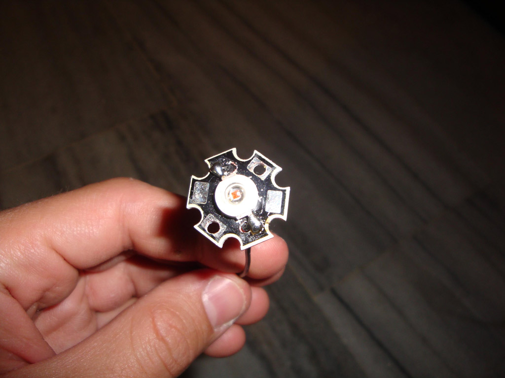
||
| A closer look from behind of how the rod was merged with the heatsink. | The Led assembled on the rod.With thermal paste applied. |
So far so good.... But how this could be fitted on the headlight ????
I must say that i was a little bit lucky because the old housing of the bulb's hole suits exactly to the rod i used.
(If i remember correct was 22mm). I removed the contacts of the old bulb housing and all it was left was the hole.
The result can be seen below....
 |
 |
 |
 |
| See how i managed to pass through the wires behind...Also how i stabilized the rod to the bulb housing. | Another photo from the frond... | Behind the mask with the protective plastic and the wires ready to be connected. | Here's how i mount the flashing led to the front light...Observe how i cutted the led to fit on. |
 |
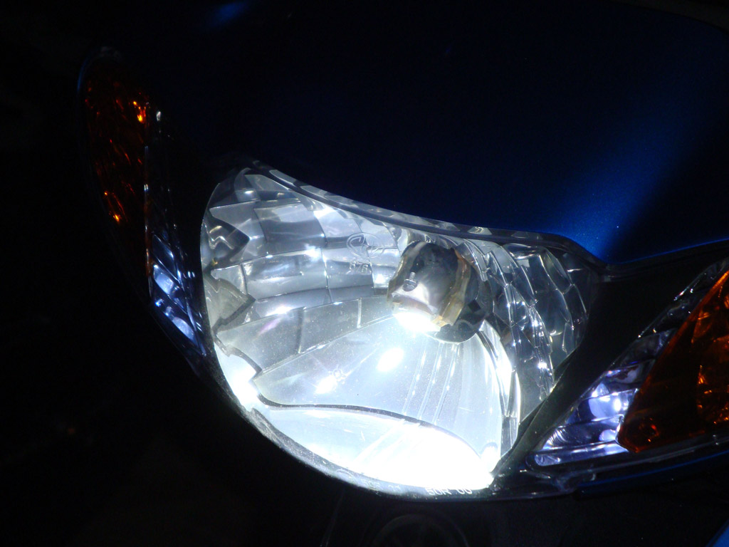 |
 |
 |
| The position lights.I soldered the led on the old bulb housing. | The led at night. (Image injustice the result). | The led at night. (Different view angle). | The led at night. (Different view angle). |
[ Speed Indicator Panel ]
Another fantastic modification was the speed indicator panel.....
I wasn't completely sure with the combination of the colors i was going to use.
My motobike as you see is light-blue. So the first color that was candidate was the blue, and the second one
was the (cold) white.
After few experiments i did, i ended that the cold white was obviously the best color that suited the panel.
So when i disassembled the panel, for my good luck again, i observed that the holes that panel have for the bulb gears,
are rounded were i consumed that 10mm leds
would fit on these holes.....
So i bought 10mm white leds for the gears and some smd leds for the panel backlight. And VOILA!!!! I was correct.
The rounded 10mm Leds were perfectly fitted on the holes with a little bit help from a drill with 9.5mm diameter so that the leds would go
into the holes cuneated.
 |
 |
 |
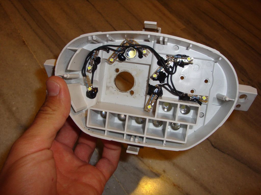 |
| The Speed indicator panel. (Notice i have painted the needles. Sun had made them fade out.) | The disassembled speed indicator panel. | The way i glued the smd leds for the backlight.(Observe the holes.) | Another view with the 10mm Led. |
Then i decided that it would be a nice idea of developimg a pcb to mount the leds and the controller on it.
So i carefully designed the pcb, after i had made my measurements using a caliper....
And believe me it wasn't so easy to alligh the leds to the panel.
(I did 3 Pcb's. The first had wrong allignment, the second had an error with the transistor polarity, and the third one was my last without errors.)
Here are the results of the final pcb....
 |
 |
 |
 |
| The front side of the pcd. (Notice that there is nothing on the front because it has to go firmly to the panel.) | The bottom side of the pcb. (Notice the connectors.) | Another look of the bottom side. | A Closer look of the bottom side. |
The connectors on pcb's bottom are for:
The 3 pin connector connects the LM7806 with the pcb (I had to fend it off because it should be placed on a heatsink.)
The 2 pin connector connects the backlight smd leds, and also an extra 10mm led for panel's backlight.
The 10 pin connector has the connections with the gears,the flasher,the big scale lights,and the power supply...
 |
 |
| The pcb mounted on the panel. (Notice the connection of the leds with the extra one.) | A different angle of the pcb mounted on the panel. |
Materials for the speed indicator panel
| Resistors | |||
| R1 -R7 | Resistor 130 Ohm | ||
| R8 - R9 | Resistor 1 KOhm | ||
| R10 - R11 | Resistor 10 KOhm | ||
| Capacitors | |||
| C1 - C2 | Electrolytic Capacitor 10 uF 35 Volts | ||
| Diodes | |||
| D1 - D2 | 1N4148 Switching Diode | ||
| D3 | 1N5819 Diode 1A 40V Schottky Rectifier | ||
| Transistors | |||
| TR1 - TR2 | BC558 PNP Epitaxial Silicon Transistor | ||
| IC's | |||
| IC1 | 7806C Positive Voltage Regulator | ||
| Leds | |||
| Led 1-7 | 10mm Rounded White Leds | ||
| Led 8-15 | Smd White Leds | ||
The board for the indicator panel

[ Flasher Circuit ]
You may have notice sometime that when a bulb of our motorcycle has been burn out, the hole flasher circuit changes the flashing rate speed.
This is because the flasher circuit uses current draw to flash the bulbs.
So when a bulb burns out the current that it is drawed is less and the flashing rate increases.
To avoid this you will have to build a new one flasher.
In my case i used a pic instead of a 555 timer, because i had to make some calculations to determine the flashing speed, and to be honest i am a little bit rested with the simplicity that microcontrollers provide....
Also you can change anytime the flashing speed by software instead of desoldering and soldering again capacitors and resistors.
I used a PIC12F615 (Donation from Kam...Thank you Kam!!!) which does all the "hard timing job".:-) .
Also the flashing speed can be customizable through software change.
The circuit is always out of power. When you turn the switch to turn left or right, the circuit gets power and turns on-off alternately the power transistor.
After that the transistor is connected in a way that supplies the flashing leds with ground through the led driver...
(See attached images to understand wiring connection.)
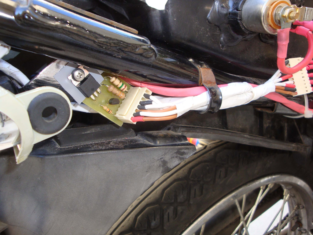
Below you will find photos from the disassembled old flasher, and my new one with the old housing.
 |
 |
 |
 |
| The old flasher disassembled. | My new compact programming customizable flasher. | Underneath Flasher pcb. | My new flasher glued with melt gun into the old housing. |
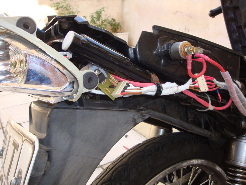
 |
 |
||
| Another angle of the flasher. | How it was placed on my motorbike. (Same as the old one). |
Materials for the flasher circuit
| Resistors | |||
| R1 | Resistor 10 KOhm | ||
| Capacitors | |||
| C1 - C2 | Electrolytic Capacitor 10 uF 35 Volts | ||
| Transistors | |||
| TR1 | BD679 Medium Power NPN Darlington Bipolar Power Transistor | ||
| IC's | |||
| IC1 | PIC12F615 Microcontroller | ||
| IC2 | 78L05 Three terminal positive voltage regulator | ||
The board and the software for the flasher circuit
[ Tail Light ]
On the tail light the only difficulty i faced, was again the way of how to consolidate the leds on the tail panel.
Since the flashing leds i used are 1W and the fact that the current they consume is about 300ma (MAX) there was no need (and after experimentation i did) to place them on a heatsink.
So i was a little bit reliefed because i wasn't worried for the flashing leds heatsink.....
The next think that i should have on mind, was to think a way, that when it would be requiered to change the leds, i wouldn't have to disassemble the whole motorcycle.....
:-) You may have noticed already that i used connectors, and polarized connectors to every led as a result everything could be easily changed...
At first i took the led and i opened to it 2 holes (for transfering the wires back).
Then i drilled the case with a smaller drill so the screw that i was going to use, to be screwdrived tightly on the rear panels plastic case.
Below are the photos....
 |
 |
 |
 |
| The Led drilled, and soldered with the wires. | A photo from the back of the led. | The drills i did for Led. | The Led on the tail panel (Screwed). |
 |
|||
| And this is how the wires passed behind, for connection with the led driver. |
Thats for the flashing leds... Now for the "Stop" led i didn't have to use a very big heatsink.
The current draw that the led consumes is about(~400ma) when i press brake switch, and it's normal conditions is about (~150ma).
 |
 |
 |
 |
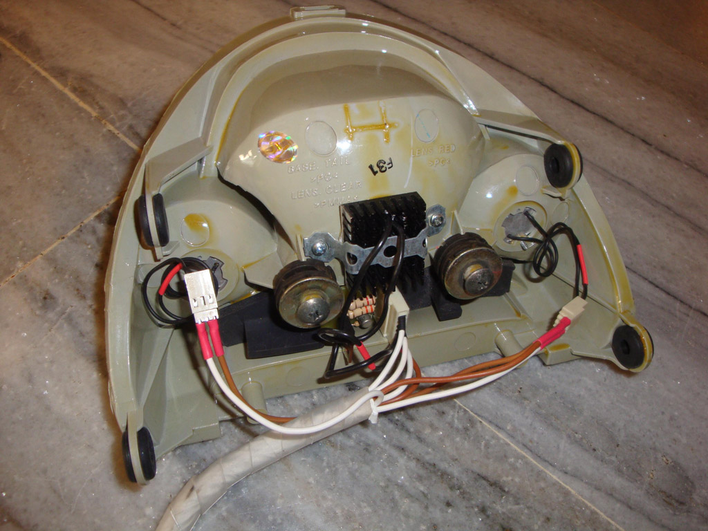
| The tail light showing the aluminium rod fitting, with the holes i created for led's mounting. | The "Stop" Led fitting, with the insulating bushing. | The tail light from behind.the polarized connectors makes perfect solution for easy changing. | The tail light "on" the motorcycle. |
Important note:
In the photo above you will notice that i have placed the led driver "on" the tail light.
I did a very big mistake because i forgot that the mosfet gets hot and should be placed on a heatsink.
So after few days when the mosfet died took with it the led.
That cause me to change position of the driver and place it on a heatsink, which was the motorcycle's chassis.
(See on Drivers below for further info.)
 |
 |
| The stop light at night. (Image injustice the result) | The stop light at night. With the flashing led on. |
[ Led Drivers ]
In this page there is no much to tell for the led drivers since you can read a very good explainatory theory from Kam (pcbheaven.com)
where describes how to build a Led driver and which one is the more efficient....
If i could turn back time, certainly i would have used a Buck-Regulating LED Driver. I would have more efficiency than now.
(Not meaning that i didn't achived efficiency right now.) So for those who would like to build led drivers it would be nice to have that consideration in mind...
Now to the project... As i previously said i used the mosfet driver.
I made a pcb for the driver and i was very satisfied with the way i mount the drivers to the motorcycle...
I built three drivers for the whole motorcycle. One for the front light, one for the flashing leds, and one for the tail light.
I mount the two of them to the front light and the other one on the chassis motocycle down of the saddle.
 |
 |
| The led driver's pcb. | A photo from the bottom side. |
Because the pcb was installed in the front light i had to separate the mosfet from the pcb because of the heatsink....
So used again the polarized connector to fend the mosfet from the pcb...
And how all this can be fitted without having problems with the vibration ???
I took 3mm threaded rod and cutted in my desired lengths.
Then with safety nuts i accomplished the stability to my drivers even when the motorcycle falls on road potholes...
 |
 |
 |
 |
| The mosfet soldered on polarized header. | The threaded rod.Cutted in pieces. | The safety nuts. | I drilled it for the drivers mounting. |
 |
 |
 |
 |
| I then passed through the threaded rod. | The drivers on the front light. | A more detailed photo from the drivers. | Another view. |
 |
 |
 |
 |
| The heatsinks i used taken from a broken tv. (Notice the one mosfet with the 7806.) | Another view of the finished front light. | This is how i mounted the back driver on the chassis acting as heatsink. | Another view of the back driver mounted on motorcycle chassis. |
[ Power Outlet ]
Another COOL and simultaneously USEFUL addition feature is the power outlet.
My job is refrigerator and air conditioning engineer. When it is possible i use my motorcycle for my transportation.
It's a good solution to move around Athens. But very often i forget to charge my UV torch i have, my cell phone, so
this power outlet would be very handy not only for this purposes...but also when you need a regulated 12v power source.
It's nothing special. It is a connector connected with a fuse holder in series with the battery after the diode rectifier (Because of the alternator).
So SIMPLE so USEFUL..... (At least to me...)
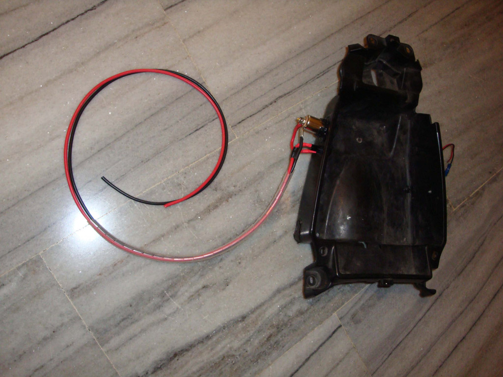 |
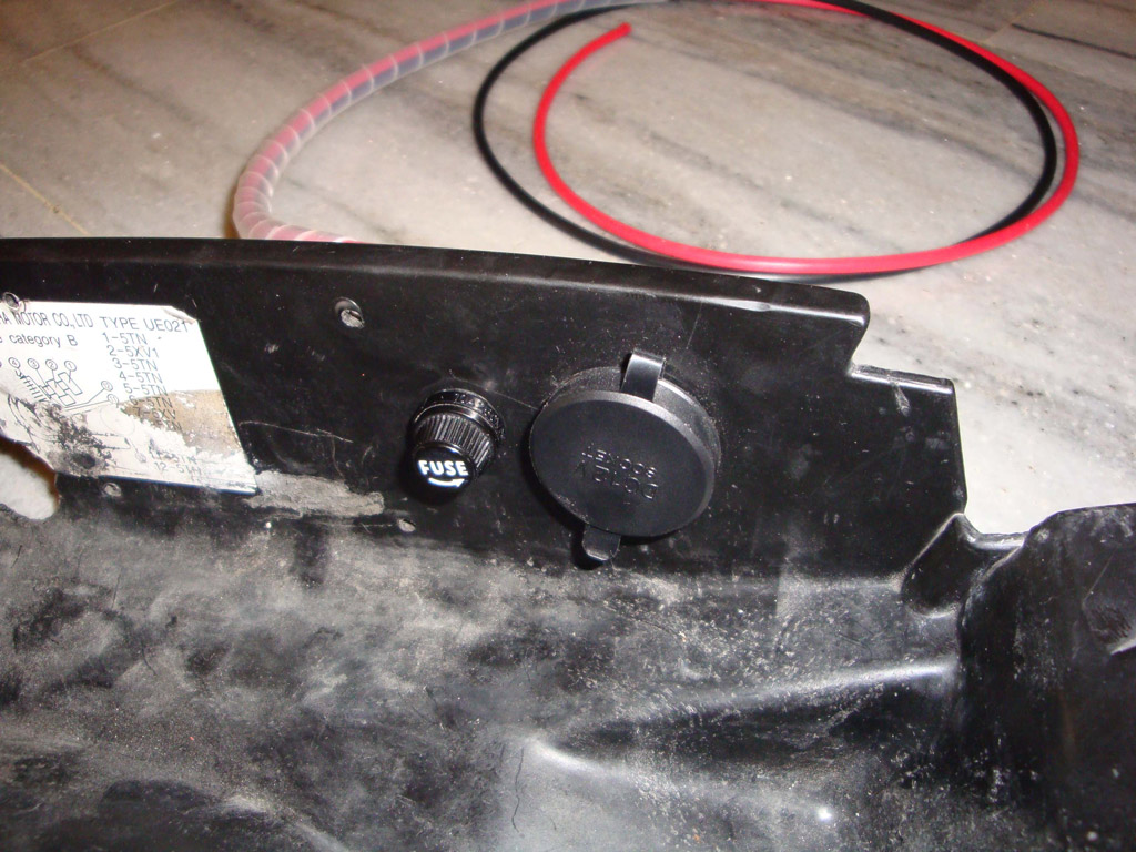 |
 |
 |
| I removed the plastic case below the saddle and drilled it to attach the connector and the fuse holder. | A closer look to the connector and the fuse holder. | A look from behind. | How it was placed on the motorcycle. |