Update Firmware on an ESP8266-01
Introduction

L14.3mm W24.8mm H3mm |
The first chip's released date was around August of 2014, where that time a third-party manufacturer named AI-Thinker
made a series of modules with this chip and with a prefix of "ESP-xx" where also comes the ESP-01 module.
Since then, we must admit that these two companies changed definitely the approach around IOT. (Internet Of Things).
There are lot of boards out there, but in this tutorial we will focus on ESP8266-01
The ESP8266 integrates a Tensilica L106 32-bit RISC processor, which achieves extra low power consumption and
reaches a maximum clock speed of 160 MHz (Overclocked).
Since there is no programmable ROM in the chip, our programs (meaning the UI and the boot ) has to be installed
in an external SPI flash. From the datasheet it can support up to 16 MB external RAM, but usually nowdays the
ESP8266-01 modules, come with an 8Mbit (1024kb) eeprom and some board improvements that we will talk later on.
ESP8266ex FEATURES :
• 802.11 b/g/n• Integrated low power 32-bit MCU
• Integrated 10-bit ADC
• Integrated TCP/IP protocol stack
• Integrated TR switch, balun, LNA, power amplifier and matching network
• Integrated PLL, regulators, and power management units
• Supports antenna diversity
• Wi-Fi 2.4 GHz, support WPA/WPA2
• Support STA/AP/STA+AP operation modes
• Support Smart Link Function for both Android and iOS devices
• Support Smart Link Function for both Android and iOS devices
• SDIO 2.0, (H) SPI, UART, I2C, I2S, IRDA, PWM
• STBC, 1x1 MIMO, 2x1 MIMO
• A-MPDU & A-MSDU aggregation and 0.4s guard interval
• Deep sleep power 10UA < 10uA
• Power down leakage current < 5uA
• Wake up and transmit packets in < 2ms
• Standby power consumption of < 1.0mW (DTIM3)
• +20dBm output power in 802.11b mode
• Operating temperature range -40C ~ 125C
• Wi-Fi Direct (P2P), soft-AP
• 1MB Flash Memory (On board eeprom memory)*
PCB Versions
So below you see the three versions of ESP8266-01 modules that are manufactured by Ai-Thinker company.
The first pcb (blue) is obsolete. This pcb was the first of the kind, and it had an external eeprom of 512kb of memory which wasn't enough to perform OTA update.
Nowdays (2020) the other two are available on e-shops, with the pcb on the right labeled as "S-Series" to be the latest and most improved version of all ESP-01 pcb's.
According Ai-Thinker, "S-Series" pcb's were re-designed to accompish greater stability, and maximize the strength of the antenna, which reaches approx 40meters.
The new pcb also misses the power led, (which finds me accordant), and there is a silkscreen pinout connection at the back of the pcb which can be very helpful,
when you are not familiar with that type of pcb.
Finally these two pcb's are equiped with a 1MB(8Mbit) of SPI Rom, where can be upgraded to 4MB(32Mbit) by simply de-soldering the old Rom chip and solder the
new one. (Like the W25Q32 from Winbond). This gives you the ability to load custom webpages, SPIFFS (Serial Peripheral Interface Flash File System) to the onboard
memory, so to work it as a standalone module, without the need of a microcontroller.
If the onboard markings makes you unable to identify the size of the Rom, later on i will show you how it can be identified by the official ESP flashing tool.

|
Pinout Description

(Click to enlarge) |
Now lets make a small analysis of the ESP8266-01 module pins.
| This is the positive power supply pin. Nominal voltage is 3.3V to 3.6V(Max) | |
| Driving this pin LOW it causes the module to Reset. | |
| Chip power down pin.(AKA Enable pin.) This pin should be pulled high in order to operate and accept commands. | |
| This is the Transmit pin of the serial communication. (TTL Logic level 3.3V) Logic shifter for 5V. | |
| This is the Ground of the module. | |
| General purpose Input / Output (2) | |
| General purpose Input / Output (0) (Also used when updating the firmware) | |
| This is the Receive pin of the serial communication. (TTL Logic level 3.3V) Logic shifter for 5V. |
The Firmware / Connections

(Click to enlarge) |
When you buy this module, it comes pre-programmed with an AT command Set Firmware on it.
This tutorial will guide you of how to update this kind of AT command set firmware, to a latest version.
Firstly you will need a USB-to-TTL Serial converter (Fig4) on the right. (Make sure to have placed the jumper to 3.3v)
That is because these days computers don't have a COM port available on their hardware, on which will be needed to communicate
with the module so to update it's firmware.
So by using a USB-to-TTL converter you create a VCP (Virtual Com Port) to your computer, which is used to convert
USB data to TTL-level UART serial data and vice versa.
I strongly recommennd you to buy a module which has an FTDI 232 chip on it.
FTDI company is specialising in USB technology, and it develops, manufactures, and supports devices and their related software
drivers for converting RS-232 or TTL serial transmissions to USB signals, and again vice versa.
Hardware connections :

(Click to enlarge) |
This is the connection i did, and you need to do, to update an ESP8266-01 firmware.
After that, once you power the circuit the ESP enters the programming mode. (Pretty simple... pretty easy...)
(A note for the power supply...) The power supply should be capable of delivering at least 1A of current to the circuit.
Now let's have a look of the software that we will use for the update.
Official flash download tool software :
Espressif systems has relesed a software that connects to ESP82xx and ESP32 devices which flashes the ROM to a latest version.
This program is named as "Flash Download Tools (ESP8266 & ESP32)" and here is the official >>> LINK <<< if you want to download it.
You will also need the latest version of the AT command set Firmware that is going to be flashed in the eeprom memory where it can be also
downloaded from Espressif official site >>> LINK <<< Just select the firmware for ESP8266ex and not for ESP32
STEP 1 :
When you have successfully downloaded and executed the program, you come accross with the screen from below.Since this flash tool can flash similar chips from Espressif, we press the button that shows the red arrow, so to flash an ESP8266 chip.

STEP 2 :
This is the main screen. Now we have to load the latest firmware that is going to be uploaded to the chip.Having downloaded the AT command set firmware , press the button (that the red arrow points) to browse
your computer, find the files, and place each file in a correct eeprom memory location.

STEP 3 :
At this point i would like to tell you that if you don't know the onboard eeprom's memory size, this tool can help you outidentifying the size by a single device read. Otherwise if you do know the memory size that it is onboard, skip this step and move on step 5.
Having connected the ESP module with the USB to TTL converter as it is in (Fig5), and having checked that the select boxes are unchecked (1)
Set your COM port in the dropdown menu (3), and press the START button (4), to initiate a read. Number (2) shows the values that we should write
manually so to each file been written to a specific location of eeprom memory. (Not necessary on this step)

STEP 4 :
When the read operation will be completed, we get a notification message from the software that it has finished, (Red arrow) and we also seethe MAC address (Underlined) with the memory size of the eeprom, in the detected info box. (Red circle).
So by a simple read we know that this eeprom has a size of 8mbit. This is crucial since we need to know which file size we should flash.

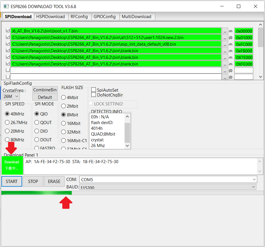
STEP 5 :
Now we are ready to flash the eeprom. Make sure that all the files are the same as it is below. (This applies to an 8Mbit eeprom and a version of 1.6.2)Also double check that you have loaded the user1.1024.new.2.bin so it can be fit into the 8Mbit the eeprom.
Set the appropriate addresses, so to match each corresponded file individually (2), check the tick boxes on the left (3), make sure that the other options
are the same (4), set your COM port (5), and hit start button (6)

STEP 6 :
As you can see a notification message appears which inform us that it is downloading (Flashing the eeprom) in combination with a progress bar.(The red arrows)
STEP 7 :
When it has finished flashing, an update notification message appears which inform us that it has finished. (The red arrows)(I don't know if it is obligatory to press the stop button, but i usually press it.)

STEP 8 :
Completed!!! You have successfully flash the eeprom on a newer AT firmware version. Now let's cross-check it...Turn off your power supply and remove the connection of GPIO_0 from ground, (Let it float). Open a serial monitor such as TeraTerm (I use Sscomm32)
or use any other available, set your COM port with a baud rate of 115200bps, check from the options CR and LF to be enabled, and turn power on.
At first you will see garbage characters, and after that a ready message. This means that the module is ready and waiting for commands.
By writing AT (1) and pressing the enter button, if evetything has gone well, you should get an answer of OK (2).
By writing AT+GMR (3) and pressing the enter button, the ESP will send you the running version.
As you can see it has been updated to the 1.6.2 version (4), and this version is made by Espressif official developers and not from Ai-Thinker (5)
(According Espressif it's the latest version that it can fit on an 8Mbit eeprom. Newer versions 1.7.0 and above can be flashed on a 16Mbit eeprom)

Failing Flashing (What went wrong?)
During flashing procedure i came accross with an unexpected error !!!.
It was so diffucult for me to figure out what went wrong, since all my setting were made according Espessif's flashing documentation.
As you can see from below at the end of the flashing procedure i received an error notification message, without analyzing anything more.

After a loooooot of trial and error, i made a thought that came true!!!. As strange as it might hears, the problem was occuring because of
the USB to TTL converter. Although both have FTDI chips on them, as many tries i did, i never succeeded flashing one of the ESP8266 modules.
I tried to spot differences between the modules, and what i found is that one of the modules has tantalum capacitors, which this is the
module that succeded flashing ESP and the markings on the FTDI chips are different which might mean different chip manufacturer.
(And perhaps not standarized materials) I will do some changes and i will post again my results.

Video
Follow me on tweeter and stay tuned with Electronicsgate.com
ESP Selection Table (Ai-Thinker)
Ai-thinker has created a table of the current production ESP-01 modules (2020) which can be revised, in order to select an appropriate module for your application.

F.A.Q.
I have found some F.A.Q that i would like to share with you since this can be very helpful to overcome problems that you might face when you experimenting
with the ESP8266. Whenever i find new F.A.Q i will upload them here.
(Question)
In the Download Tool V3.4.4 what is:
(a) Device Master Key ?
> You may ignore the field (leave it as it is) right now. It is not a functional official feature as of right now. We will update on it soon.
(b) the correct setting for the SPI Mode on the WROOM-02 ?
> You may go for QIO mode on this one. DIO will work on pretty much every module.
(c) the Xtal frequency and SPI speed on the WROOM-02 ?
> The crystal frequency is 26 MHz
(Question)
In the ESP8266 NONOS_SDK V2.0.0_16_08_10
(a) There are 2 folders "at" and "at_sdio". I assume at_sdio uses the SIO port for I/O instead of the UART ?
> Yes, at is for UART based communication, and at_sdio for SDIO based systems.
(b) Where is the documentation about how to use the SIO port for AT commands ?
> The SDIO based system uses the same commands as the UART mode. The SDIO interface is an international standard and therefore,
there is no specific
device-level documentation required. You may refer to standard SDIO rev.2.0 documentation.
(c) In the file at/readme.md it says #BOOT MODE and #NON-BOOT MODE. What is the difference between these modes ?
> Boot mode is when you use user1.bin and user2.bin and that helps implement online updates for ESP8266. In non-boot mode, there is no provision for supplying
online updates to firmware over WiFi. Please refer to the FAQ and Getting Started Guide for more information: www.espressif.com/products/hardware/esp8266ex
(d) In the file at/readme.md it shows how it can be flashed OTA. How do you tell it which of at or at sdio you want to be flashed ?
> Please use the UPDATE AT command for updating the flash OTA. The firmware knows which type it is (set at the time of compiling) and boot.bin handles
the stuff that determines how to proceed with flashing an update.
(e) When using the flash tool, the 4 files mentioned i.e. boot,,,, user,,,, esp_init.... blank.... are sufficient to flash the device ?
> Yes, boot BIN manages booting and flash updates. User BIN is the main application BIN (user1 and user2 are updated alternatively, so that the device is not
bricked
if a flash update fails without properly completing. One of the BINs is definitely reliable at all times).
Init BIN contains initialization parameters and blank BIN is used to erase some sectors that store application information.
(Question)
What does "busy" , "busy s..." and "busy p..." means ?
> "busy" means that the previous AT command is not finished yet, so we cannot accept the next AT command.
> "busy p" means command is doing.
> "busy s" means sending data is doing.
(Question)
What is is the required time between each packets transmition ?
> We need to wait 20ms between each packets .
(Question)
What is is the maximum transmition byte length ?
> Maximum length is 2048 bytes per packet.
(Question)
What is is the difference between "at" and "at_sdio" ?
> "at" uses UART to send AT commands.
> "at_sdio" uses SDIO.
(Question)
After a change on UART speed i can't get any response of the ESP8266. Is it possible to have it bricked ?
> We suggest when using "UART_CUR" which would not be saved in flash to try the new configuration first, if it can not work,
you can just power off and power on to recover.
The last parameter "3" means UART flow control which needs your UART hardware to support flow control.
Maybe you could try to connect the CTS、RTS, and enable the flow control on your UART tool, and try again.
If it does not work, you need to re-download AT firmware to your module to recover.
(Question)
What is SSPIFFS ?
> SSPIFFS stands for SPI Flash File System
It's a light-weight file system for microcontrollers in an SPI flash chip. The on-board flash of ESP8266 has plenty of space for our webpages, especially the 4MB version.
For those who have played with ESP8266 will know that our webpages are stored as strings in our code or data words for each pair of 2 bytes of 8bit length.
This makes the code to be very hard to read, and soon you'll run out of mcu memory.
SPIFFS let's you access the flash memory as if it was a normal file system like the one on your computer (but much simplier) as a result to read, write files and create
folders in the flash memory.